A TRIAC (Triode for Alternating Current) is a three-terminal semiconductor device that acts as a bidirectional switch. It is a member of the thyristor family and is equivalent to two Silicon-Controlled Rectifiers (SCRs) connected back-to-back in a single package.
Why use a TRIAC?
The primary reason to use a TRIAC is its ability to control AC power in both directions of the sinusoidal cycle.
Full-Wave Control: Unlike standard SCRs, which only conduct in one direction (handling only half the AC wave), a TRIAC handles the entire cycle with a single component.
Simplified Circuitry: Using one TRIAC instead of two SCRs reduces the number of components, simplifies the gate triggering circuit, and saves space.
Flexible Triggering: It can be turned on with either a positive or negative signal to its gate, regardless of the polarity of the AC supply.
Importance and Key Functions
TRIACs are vital in modern electronics because they provide a bridge between low-power control signals (like from a microcontroller) and high-power AC loads.
Phase Control: By delaying the exact point in each AC cycle when the TRIAC “fires” (turns on), it can precisely regulate the average power delivered to a load.
Smooth Dimming: This phase control is the “backbone” of modern light dimmer switches, allowing for flicker-free brightness adjustment.
Variable Speed Control: They are essential for regulating the speed of AC motors in appliances like fans, blenders, and washing machines.
Heating Management: TRIACs provide precise temperature regulation in electric ovens, water heaters, and industrial furnaces by modulating the power sent to heating elements.
Solid-State Reliability: Because they have no moving parts, TRIACs serve as long-lasting solid-state relays (SSRs) that switch much faster and more reliably than mechanical switches.
In an AC (Alternating Current) circuit, the behavior of the TRIAC changes fundamentally because the voltage and current are constantly reversing direction and, most importantly, passing through zero.
1. The Zero-Crossing Effect
In AC, the sine wave crosses the 0V mark 100 times per second (for 50Hz) or 120 times per second (for 60Hz).
The Rule: A TRIAC will automatically turn OFF whenever the current flowing through it drops below its “holding current” threshold.
The Result: Every time the AC sine wave hits zero, the TRIAC “unlatches” and resets to its non-conducting state.
2. Step-by-Step AC Operation
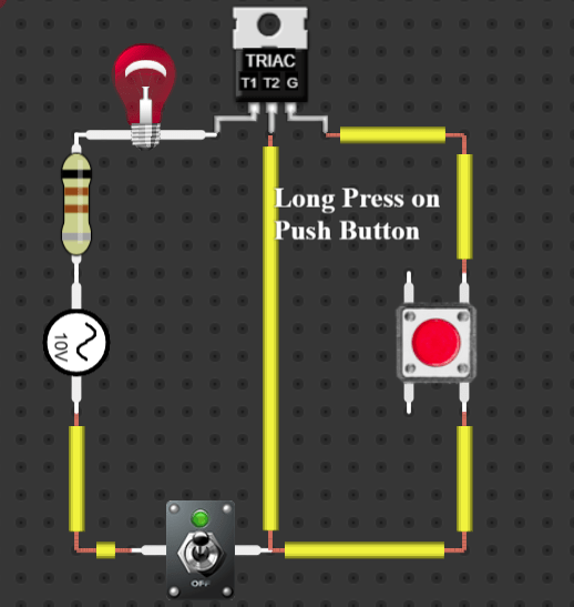
Step 1: Standby The main toggle switch is ON. The AC sine wave is oscillating, but since no signal has hit the Gate (G), the TRIAC remains an open switch. The bulb is OFF.
Step 2: Triggering (The Push Button) You press the red push button. A small amount of AC current enters the Gate. The TRIAC triggers and allows current to flow between T1 and T2. The bulb turns ON.
Step 3: The “Instant” Off As soon as you release the push button, the Gate signal stops. Within a fraction of a second (less than 1/100th of a second), the AC sine wave reaches the zero-crossing point.
Step 4: Failure to Latch Because the current hit zero, the TRIAC turns OFF. Since your finger is no longer on the button to “re-trigger” it for the next half of the sine wave, the TRIAC stays OFF. The bulb turns OFF immediately.
3. Summary Table: DC vs. AC
Feature
DC Circuit (Your Image)
AC Circuit
Current Flow
One direction, steady.
Reverses direction (Sine wave).
Latching
Yes. Stays on until the switch is flipped.
No. Turns off at every zero-crossing.
Push Button
Acts like a “Start” button.
Acts like a “Momentary” switch.
Bulb Behavior
Stays ON after one click.
Only stays ON while holding the button.
How do we keep it “ON” in AC?
In real-world AC applications (like a lamp dimmer), we don’t use a manual push button. Instead, we use a Triggering Circuit (usually a resistor and a capacitor) that automatically “shouts” at the Gate to turn back on at the start of every single half-cycle.
Because this happens so fast (100+ times a second), the human eye cannot see the bulb turning off and on; it just looks like a steady light.
This project focuses on the design and implementation of a Short Circuit Detection system in the DCAClab circuit simulator. A short circuit occurs when an unintended low-resistance path is created, causing excessive current flow that can damage components, overheat circuits, or pose safety hazards. Our system monitors current and voltage in real-time to identify abnormal conditions indicative of a short circuit. Once detected, the system triggers alerts, helping users prevent potential circuit damage and ensuring safe operation within the simulation environment. This implementation serves as both a practical educational tool and a prototype for real-world short circuit monitoring systems.
Introduction
Short circuit detection refers to the process of identifying when an unintended low-resistance connection occurs in an electronics or electrical circuit, typically between two points where it shouldn’t exist. This abnormal connection causes a large current to flow, potentially leading to damage, overheating, or even fire. Detecting short circuits is crucial for protecting electrical components, systems, and personnel.
In DCAClab Circuit Simulator – Real Time Short Circuit Detection – a feature that sets a new industry standard in educational and professional circuit simulation tools. DCAClab is now among the first in its category to intelligently detect and respond to short circuit conditions in real time, ensuring both a realistic simulation experience and a deeper understanding of circuit behavior.
Why Short Circuit Detection Matters
In real-life electronics and electrical systems, short circuits are dangerous faults that can damage components, overheat wires, or even start fires. In a virtual lab environment, it is crucial that students and professionals learn to recognize and avoid these conditions. Our advanced short circuit detection brings real-world consequences into the simulator, enhancing both safety awareness and design accuracy.
How DCAClab Detects Short Circuits Intelligently
DCAClab’s short circuit detection engine is built using advanced algorithms that analyze current paths, voltage drops, and impedance behavior in real-time. Here’s how it works in different scenarios:
1. Short Circuit Between Power Supply Terminals
If we directly connect the positive (+) and negative (−) terminals of a voltage or current source using a single wire with negligible resistance, the simulator will immediately detect a short circuit.
What happens in DCAClab:
A visual warning is triggered
A Red colored indicator
This helps users understand why a direct connection across the source terminals is dangerous, mirroring what would happen in a physical lab environment.
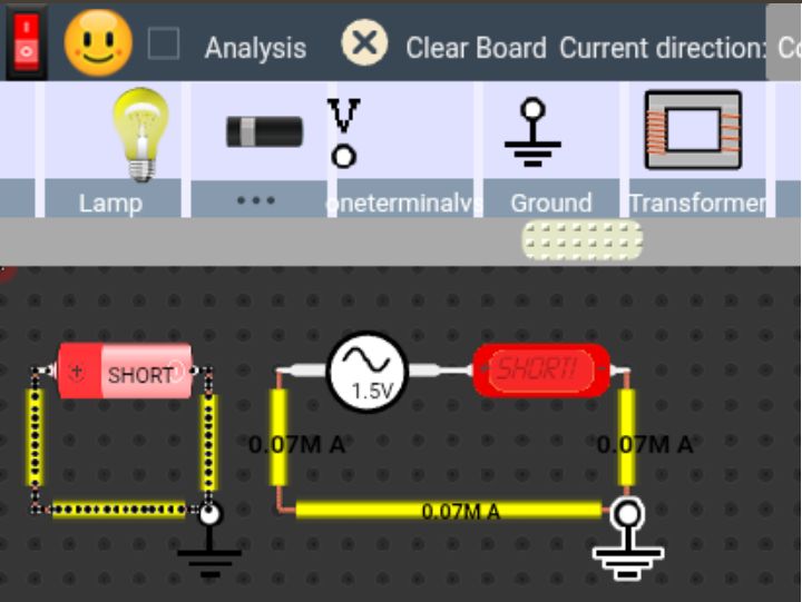
2. Short Circuit Through Incorrect Ammeter Usage
A common mistake in circuits is placing an ammeter in parallel with a voltage source or component. Since an ideal ammeter has nearly zero resistance, this creates a low-resistance path, leading to a potential short circuit.
DCAClab’s response:
Detects when the ammeter is incorrectly placed
Highlights the short-circuit current path
Warns the user and provides correction advice
This ensures users not only fix the circuit but also learn proper instrumentation practices.
3.Short Circuit via Low-Impedance Reactive Components
In AC circuits, components like capacitors and inductors can behave as very low impedance paths at certain frequencies, especially when:
Capacitors act like a wire at high frequency
Inductors act like a wire at low frequency
DCAClab now simulates this frequency-dependent behavior. If the impedance of a component drops too low due to circuit configuration or signal characteristics, it triggers a dynamic short circuit warning.
High Frequency in Capacitor
Low Frequency in Inductor
Educational Value:
Users understand the frequency behavior of reactance
See real-time impedance graphs and explanations
Gain insight into concepts like resonance and filter failure
4. Incorrect Grounding and Loop Creation
If a user creates an unintentional loop between power terminals or ground points with no load or resistance, the simulation recognizes this as a zero-impedance path and notifies the user of the short circuit condition.
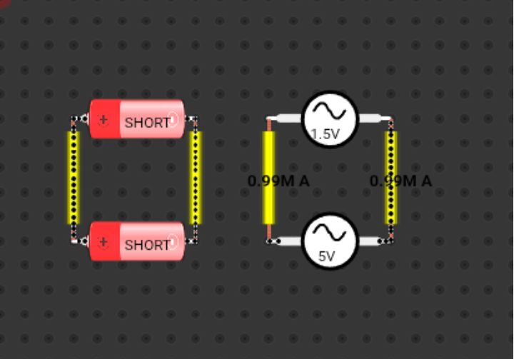
5. Parallel Voltage Sources
Short Circuit is occured when two voltage sources are connected in parallel with different voltages. To show AC short circuit, DMM or Ammeter is required in DCAClab.
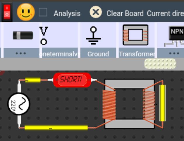
6. Secondary Coil Shorted Directly in Transformer
7. Diode or Diode Bridge Shorted in AC Source
8. Relay Short Circuit for 0 resistance of coil
In the relay, the coil has a certain resistance that limits the current flow. By setting the resistance to 0, there is no resistance to oppose the flow of current. As a result, the current flows uncontrollably, leading to an excessive flow of current through the circuit. This is essentially a short circuit condition.
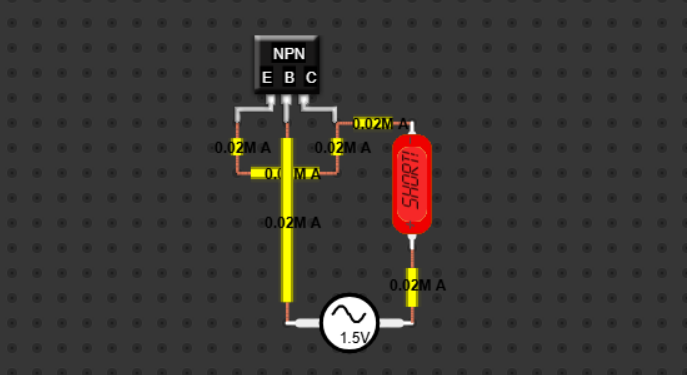
9. Emmiter and Collector directly short in Transistor
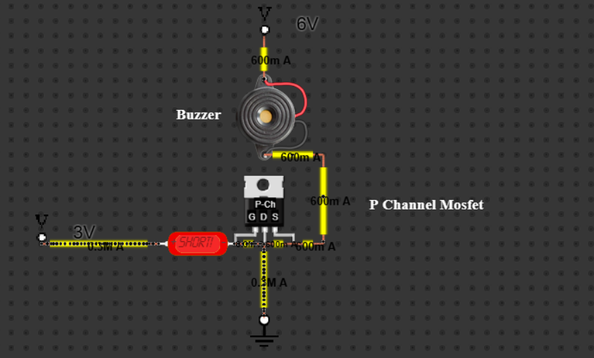
10. Gate, Source and Drain Direcly Short in P and N Channel Mosfet
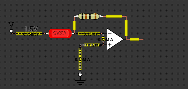
11. Opamp Short Circuit
Short Circuit Types – Summary Table
Category
Example
Triggered in DCAClab
Power Supply Short
Wire directly between + and − of a voltage source
Yes
Ammeter Misuse
Ammeter placed in parallel with resistor or voltage source
Yes
Capacitor Reactance (AC)
Capacitor in high-frequency AC circuit behaving as short
Yes
Inductor Reactance (AC)
Inductor in low-frequency AC circuit behaving as short
Yes
Ground Loop
Multiple grounds directly connected without load
Yes
Infinite Loop Path
Wire loop with no resistance or load
Yes
Internal Component Fault
Shorted transistor (e.g., collector-emitter)
Yes
Parallel Voltage Sources
Two voltage sources connected in parallel with different voltages
Yes
Op-Amp Misconnection
Output shorted to input or power rails or direct short
Yes
Transformer Short
Secondary coil shorted directly
Yes
Capacitor Charged & Shorted
Charged capacitor terminals shorted suddenly
Yes
Miswired Bridge Rectifier
AC input shorted across DC output terminals
Yes
Electrolytic Capacitor Error
Polarity reversed on polarized capacitor
Yes
Relay Short Circuit
When set up 0 resistance of coil
Yes
Key Features of DCAClab’s Short Circuit Detection
Real-time monitoring of current paths and node voltages
Intelligent analysis of impedance across all components
Frequency-aware behavior for AC analysis
Realistic modeling of ammeter and voltmeter internal resistance
Friendly educational messages and correction suggestions
Helps prevent component damage in simulation
Visually highlights short circuit paths for easy troubleshooting
Built for Learners, Loved by Professionals
DCAClab isn’t just about circuit building — it’s about learning and mastering electrical and electronic design. This new short circuit detection system encourages users to:
Think critically about their circuit layout
Understand electrical safety principles
Learn the real-world behavior of components and instruments
Develop diagnostic skills useful for engineering careers.
Conclusion:
Short circuit detection is essential for ensuring the safety and reliability of electrical and electronic systems. By identifying unintended low-resistance connections promptly, it prevents excessive current flow, protects components from damage, reduces the risk of overheating or fire, and safeguards personnel. Effective short circuit detection is a critical aspect of circuit design and maintenance.
References:
Osman, M., & Habiballah, I. O. (2021). A Review of Short-Circuit Fault Analysis and Novel Fault Detection Methods. International Journal of Engineering Research & Technology (IJERT), 10(12). (IJERT)
Santos, A. d. S., Faria, L. T., Lopes, M. L. M., Lotufo, A. D. P., & Minussi, C. R. (2022). Efficient Methodology for Detection and Classification of Short-Circuit Faults in Distribution Systems with Distributed Generation. Sensors, 22(23), 9418. (MDPI)
Brito Palma, L. (2024). Hybrid Approach for Detection and Diagnosis of Short-Circuit Faults in Power Transmission Lines. Energies, 17(9), 2169. (MDPI)
“A New Method of Early Short Circuit Detection.” (n.d.). ResearchGate PDF. (ResearchGate)
“Detection of Inter-Turn Short-Circuit Faults for Inverter-Fed Induction Machines.” (2025). Sensors, 25(15), 4844. (MDPI)
Zhang, C., & Zhang, X. P. (2024). Bus Short-Circuit Fault Detection and Repair Technology for Improving Inverter System Reliability. Open Access Library Journal, 11, 1-15. (SCIRP)
“A Review of Winding Short-Circuit Fault and Irreversible Demagnetization Fault in PMSM: Diagnosis Techniques.” (2021). Energies, 11(12), 3309. (MDPI)
“Review of Short Circuit and Fault Analysis in Power Systems.” (n.d.). International Journal for Technological Research in Engineering. (IJTRE)
“A Literature Review of Fault Detection and Diagnostic Methods in Inverters.” (2022). Machines, 12(9), 631. (MDPI)
“Universal Short-Circuit and Open-Circuit Fault Detection for an Inverter.” (2024). Conference Paper. (old.curent.utk.edu)
“Short and Open Circuit Faults Study in the PV System Inverter.” (n.d.). SemanticsScholar PDF. (Semantic Scholar)
“An Effective Methodology for Short-Circuit Calculation of Power Systems Dominated by Power Electronics Converters Considering Unbalanced Voltage Conditions and Converter Limits.” (2022). arXiv preprint. (arXiv)
“Incipient Fault Detection in Power Distribution System: A Time-Frequency Embedded Deep Learning Based Approach.” (2023). arXiv preprint. (arXiv)
Cai, T., Mohtat, P., Stefanopoulou, A. G., & Siegel, J. B. (2020). Li-ion Battery Fault Detection in Large Packs Using Force and Gas Sensors. arXiv preprint. (arXiv)
“DCACLab – Online Circuit Simulator for STEM Education.” (n.d.). DCACLab official website. (DCACLab)


