A Comprehensive Study and Research on Short Circuit Detection Feature in DCAClab

Abstract:

This project focuses on the design and implementation of a Short Circuit Detection system in the DCAClab circuit simulator. A short circuit occurs when an unintended low-resistance path is created, causing excessive current flow that can damage components, overheat circuits, or pose safety hazards. Our system monitors current and voltage in real-time to identify abnormal conditions indicative of a short circuit. Once detected, the system triggers alerts, helping users prevent potential circuit damage and ensuring safe operation within the simulation environment. This implementation serves as both a practical educational tool and a prototype for real-world short circuit monitoring systems.

Introduction

Short circuit detection refers to the process of identifying when an unintended low-resistance connection occurs in an electronics or electrical circuit, typically between two points where it shouldn’t exist. This abnormal connection causes a large current to flow, potentially leading to damage, overheating, or even fire. Detecting short circuits is crucial for protecting electrical components, systems, and personnel.

In DCAClab Circuit Simulator – Real Time Short Circuit Detection – a feature that sets a new industry standard in educational and professional circuit simulation tools. DCAClab is now among the first in its category to intelligently detect and respond to short circuit conditions in real time, ensuring both a realistic simulation experience and a deeper understanding of circuit behavior.

Why Short Circuit Detection Matters

In real-life electronics and electrical systems, short circuits are dangerous faults that can damage components, overheat wires, or even start fires. In a virtual lab environment, it is crucial that students and professionals learn to recognize and avoid these conditions. Our advanced short circuit detection brings real-world consequences into the simulator, enhancing both safety awareness and design accuracy.

How DCAClab Detects Short Circuits Intelligently

DCAClab’s short circuit detection engine is built using advanced algorithms that analyze current paths, voltage drops, and impedance behavior in real-time. Here’s how it works in different scenarios:

1. Short Circuit Between Power Supply Terminals

If we directly connect the positive (+) and negative (−) terminals of a voltage or current source using a single wire with negligible resistance, the simulator will immediately detect a short circuit.

Infinite loop for no load

What happens in DCAClab:

  • A visual warning is triggered
  • A Red colored indicator

This helps users understand why a direct connection across the source terminals is dangerous, mirroring what would happen in a physical lab environment.

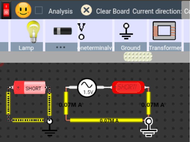
2. Short Circuit Through Incorrect Ammeter Usage

A common mistake in circuits is placing an ammeter in parallel with a voltage source or component. Since an ideal ammeter has nearly zero resistance, this creates a low-resistance path, leading to a potential short circuit.

Placing ammeter in parallal

DCAClab’s response:

  • Detects when the ammeter is incorrectly placed
  • Highlights the short-circuit current path
  • Warns the user and provides correction advice

This ensures users not only fix the circuit but also learn proper instrumentation practices.

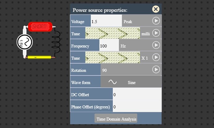
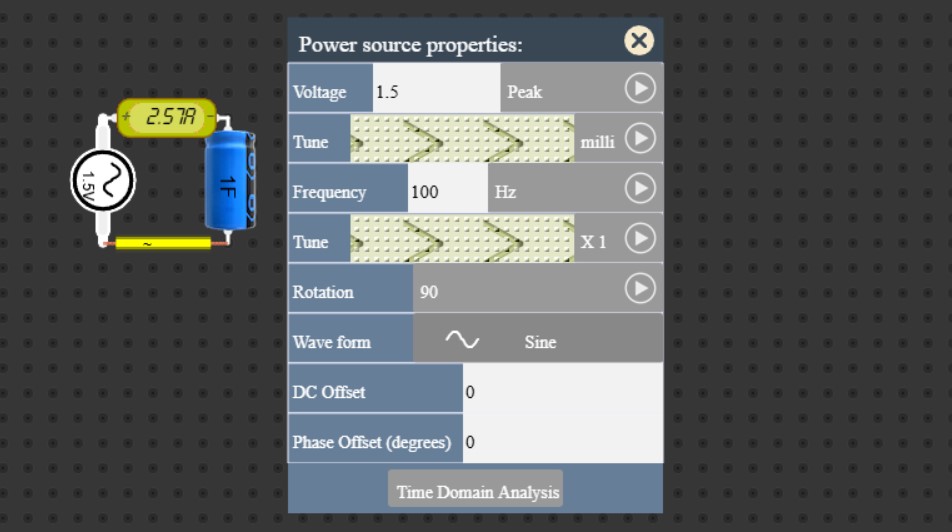
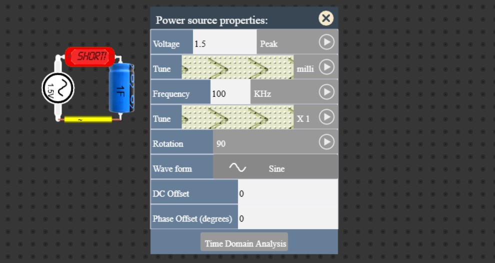
3.Short Circuit via Low-Impedance Reactive Components

In AC circuits, components like capacitors and inductors can behave as very low impedance paths at certain frequencies, especially when:

  • Capacitors act like a wire at high frequency
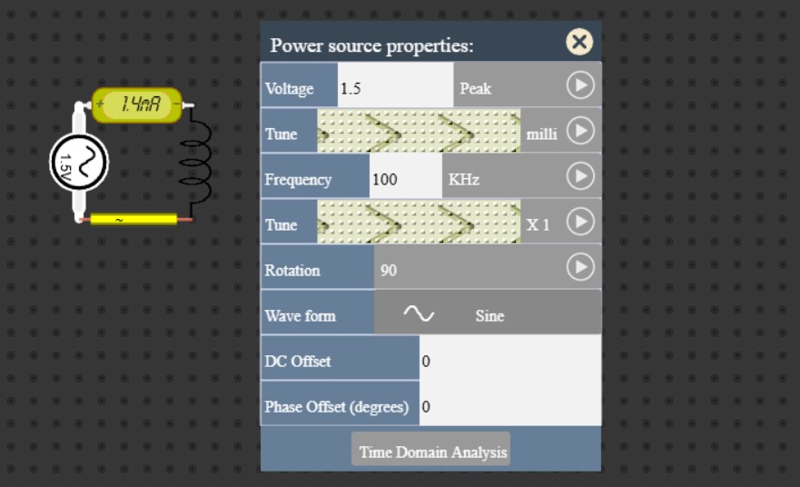
  • Inductors act like a wire at low frequency

DCAClab now simulates this frequency-dependent behavior. If the impedance of a component drops too low due to circuit configuration or signal characteristics, it triggers a dynamic short circuit warning.

High Frequency in Capacitor

High Frequency in capacitor

Low Frequency in Inductor

Low Frequency in Inductor

Educational Value:

  • Users understand the frequency behavior of reactance
  • See real-time impedance graphs and explanations
  • Gain insight into concepts like resonance and filter failure

4. Incorrect Grounding and Loop Creation

If a user creates an unintentional loop between power terminals or ground points with no load or resistance, the simulation recognizes this as a zero-impedance path and notifies the user of the short circuit condition.

Ground with no load

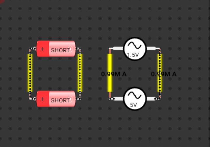
5. Parallel Voltage Sources

Short Circuit is occured when two voltage sources are connected in parallel with different voltages. To show AC short circuit, DMM or Ammeter is required in DCAClab.

parallal voltage sources

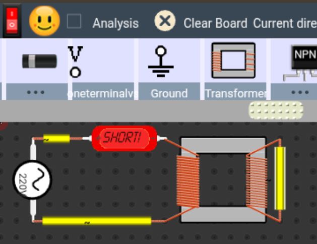
6. Secondary Coil Shorted Directly in Transformer

Secondary coil short

7. Diode or Diode Bridge Shorted in AC Source

Diode or Diode bridge short

8. Relay Short Circuit for 0 resistance of coil

In the relay, the coil has a certain resistance that limits the current flow. By setting the resistance to 0, there is no resistance to oppose the flow of current. As a result, the current flows uncontrollably, leading to an excessive flow of current through the circuit. This is essentially a short circuit condition.

Relay Short Circuit

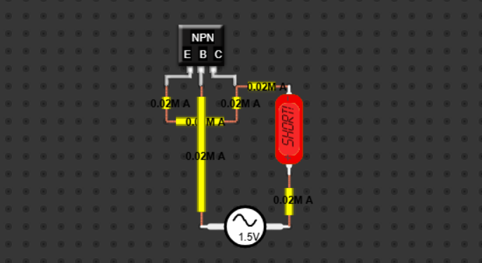
9. Emmiter and Collector directly short in Transistor

collector-emitter short in NPN Transistor

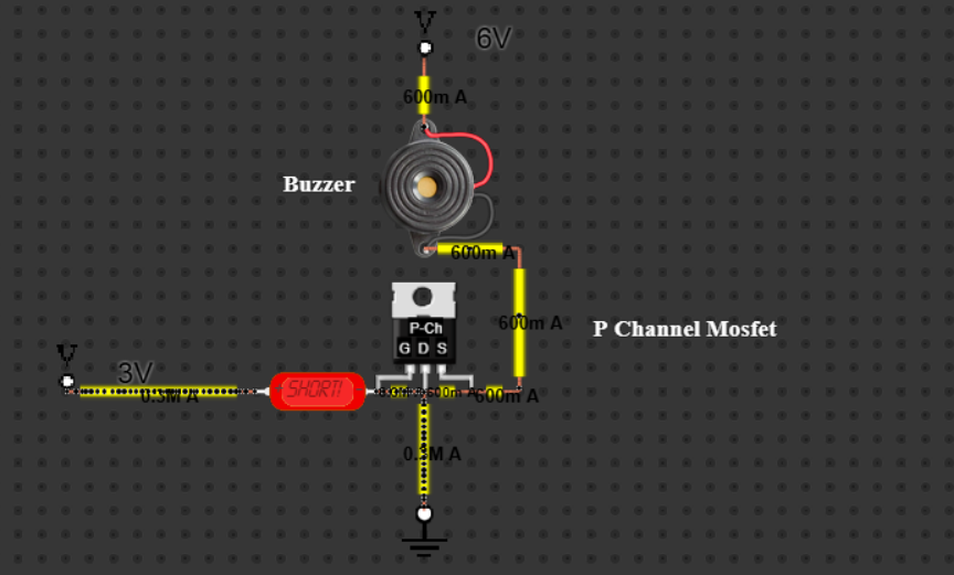
10. Gate, Source and Drain Direcly Short in P and N Channel Mosfet

Gate-Source-Drain Short

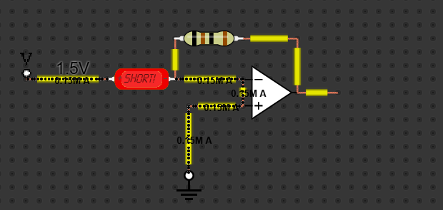
11. Opamp Short Circuit

Opamp Short Circuit

Short Circuit Types – Summary Table

CategoryExampleTriggered in DCAClab
Power Supply ShortWire directly between + and − of a voltage sourceYes
Ammeter MisuseAmmeter placed in parallel with resistor or voltage sourceYes
Capacitor Reactance (AC)Capacitor in high-frequency AC circuit behaving as shortYes
Inductor Reactance (AC)Inductor in low-frequency AC circuit behaving as shortYes
Ground LoopMultiple grounds directly connected without loadYes
Infinite Loop PathWire loop with no resistance or loadYes
Internal Component FaultShorted transistor (e.g., collector-emitter)Yes
Parallel Voltage SourcesTwo voltage sources connected in parallel with different voltagesYes
Op-Amp MisconnectionOutput shorted to input or power rails or direct shortYes
Transformer ShortSecondary coil shorted directlyYes
Capacitor Charged & ShortedCharged capacitor terminals shorted suddenlyYes
Miswired Bridge RectifierAC input shorted across DC output terminalsYes
Electrolytic Capacitor ErrorPolarity reversed on polarized capacitorYes
Relay Short CircuitWhen set up 0 resistance of coilYes

Key Features of DCAClab’s Short Circuit Detection

  • Real-time monitoring of current paths and node voltages
  • Intelligent analysis of impedance across all components
  • Frequency-aware behavior for AC analysis
  • Realistic modeling of ammeter and voltmeter internal resistance
  • Friendly educational messages and correction suggestions
  • Helps prevent component damage in simulation
  • Visually highlights short circuit paths for easy troubleshooting

Built for Learners, Loved by Professionals

DCAClab isn’t just about circuit building — it’s about learning and mastering electrical and electronic design. This new short circuit detection system encourages users to:

  • Think critically about their circuit layout
  • Understand electrical safety principles
  • Learn the real-world behavior of components and instruments
  • Develop diagnostic skills useful for engineering careers.

Conclusion:

Short circuit detection is essential for ensuring the safety and reliability of electrical and electronic systems. By identifying unintended low-resistance connections promptly, it prevents excessive current flow, protects components from damage, reduces the risk of overheating or fire, and safeguards personnel. Effective short circuit detection is a critical aspect of circuit design and maintenance.

References:

  1. Osman, M., & Habiballah, I. O. (2021). A Review of Short-Circuit Fault Analysis and Novel Fault Detection Methods. International Journal of Engineering Research & Technology (IJERT), 10(12). (IJERT)
  2. Santos, A. d. S., Faria, L. T., Lopes, M. L. M., Lotufo, A. D. P., & Minussi, C. R. (2022). Efficient Methodology for Detection and Classification of Short-Circuit Faults in Distribution Systems with Distributed Generation. Sensors, 22(23), 9418. (MDPI)
  3. Brito Palma, L. (2024). Hybrid Approach for Detection and Diagnosis of Short-Circuit Faults in Power Transmission Lines. Energies, 17(9), 2169. (MDPI)
  4. “A New Method of Early Short Circuit Detection.” (n.d.). ResearchGate PDF. (ResearchGate)
  5. “Detection of Inter-Turn Short-Circuit Faults for Inverter-Fed Induction Machines.” (2025). Sensors, 25(15), 4844. (MDPI)
  6. Zhang, C., & Zhang, X. P. (2024). Bus Short-Circuit Fault Detection and Repair Technology for Improving Inverter System Reliability. Open Access Library Journal, 11, 1-15. (SCIRP)
  7. “A Review of Winding Short-Circuit Fault and Irreversible Demagnetization Fault in PMSM: Diagnosis Techniques.” (2021). Energies, 11(12), 3309. (MDPI)
  8. “Review of Short Circuit and Fault Analysis in Power Systems.” (n.d.). International Journal for Technological Research in Engineering. (IJTRE)
  9. “A Literature Review of Fault Detection and Diagnostic Methods in Inverters.” (2022). Machines, 12(9), 631. (MDPI)
  10. “Universal Short-Circuit and Open-Circuit Fault Detection for an Inverter.” (2024). Conference Paper. (old.curent.utk.edu)
  11. “Short and Open Circuit Faults Study in the PV System Inverter.” (n.d.). SemanticsScholar PDF. (Semantic Scholar)
  12. “An Effective Methodology for Short-Circuit Calculation of Power Systems Dominated by Power Electronics Converters Considering Unbalanced Voltage Conditions and Converter Limits.” (2022). arXiv preprint. (arXiv)
  13. “Incipient Fault Detection in Power Distribution System: A Time-Frequency Embedded Deep Learning Based Approach.” (2023). arXiv preprint. (arXiv)
  14. Cai, T., Mohtat, P., Stefanopoulou, A. G., & Siegel, J. B. (2020). Li-ion Battery Fault Detection in Large Packs Using Force and Gas Sensors. arXiv preprint. (arXiv)
  15. “DCACLab – Online Circuit Simulator for STEM Education.” (n.d.). DCACLab official website. (DCACLab)

Main Source: A Comprehensive Study and Research on Short Circuit Detection Feature in DCAClab

Mesh Current Analysis in DCAClab

1. Find out the number of mesh loops:

Screenshot 2025-01-31 141359

From the circuit, we can see two independent mesh loops:

:one: Mesh 1 (Left Loop): (V1, R1, R2, R3)
:two: Mesh 2 (Right Loop): (V2, R3, R4, R5)

So, the number of mesh loops = 2.

2. Find out the current flow direction in every mesh loop:

Screenshot_20250130_150602_Chrome

We assume clockwise (CW) current flow in each loop unless otherwise specified:

:heavy_check_mark: Mesh 1: Current ( I1 ) flows clockwise (CW).
:heavy_check_mark: Mesh 2: Current ( I2 ) flows clockwise (CW).

Both currents ( I1 ) and ( I2 ) interact at ( R3 ).

3. Find out all resistors’ polarity in every mesh loop:

The polarity across each resistor is determined by the current direction:

For Mesh 1:

  • (R1): Left side (+), Right side (-)
  • (R2): Left side (-), Right side (+)
  • (R3): Top side (+), Bottom side (-)
  • (V1)

For Mesh 2:

  • (R4): Left side (+), Right side (-)
  • (R5): Top side (+), Bottom side (-)
  • (R3): Top side (-), Bottom side (+)
  • (V2)

At (R3), both (I1) and (I2) flow in opposite directions, so the net voltage drop depends on their magnitudes.

4. Use KVL law in every mesh loop:

Applying Kirchhoff’s Voltage Law (KVL):

Screenshot 2025-01-31 141359

For Mesh 1:

V1 – (I1 R1) – (I1 R2) – (I1 – I2) R3 = 0
or, V1 – I1 (R1 + R2 + R3) + I2 R3 = 0

For Mesh 2:

V2 – (I2 R4) – (I2 R5) – (I2 – I1) R3 = 0
or, V2 – I2 (R3 + R4 + R5) + I1 R3 = 0

These equations can be solved to find (I1) and (I2).

Mesh Analysis Solution

Step 1: Identify Mesh Loops

The circuit has two independent mesh loops:

  1. Mesh 1 (Left Loop): Contains V1, R1, R2, R3.
  2. Mesh 2 (Right Loop): Contains V2, R3, R4, R5.

Step 2: Assign Mesh Currents

  • Let I1 be the mesh current for Mesh 1 (Clockwise).
  • Let I2 be the mesh current for Mesh 2 (Clockwise).
  • R3 is a shared resistor between both meshes.

Step 3: Apply Kirchhoff’s Voltage Law (KVL)

Using KVL for each loop:

For Mesh 1 (Left Loop):

Applying KVL,

V1 – (I1 * R1) – (I1 * R2) – (I1 – I2) * R3 = 0

Substituting values V1 = 10V, R1 = 1Ω, R2 = 2Ω, R3 = 3Ω:

10 – (I1 * 1) – (I1 * 2) – (I1 – I2) * 3 = 0

Simplifying,

10 – I1 – 2I1 – 3I1 + 3I2 = 0

10 – 6I1 + 3I2 = 0

6I1 – 3I2 = 10 —-(Equation 1)

For Mesh 2 (Right Loop):

Applying KVL,

V2 – (I2 * R4) – (I2 * R5) – (I2 – I1) * R3 = 0

Substituting values V2 = 10V, R4 = 4Ω, R5 = 5Ω, R3 = 3Ω:

10 – (I2 * 4) – (I2 * 5) – (I2 – I1) * 3 = 0

Simplifying,

10 – 4I2 – 5I2 – 3I2 + 3I1 = 0

10 + 3I1 – 12I2 = 0

3I1 – 12I2 = -10 —-(Equation 2)

Step 4: Solve for I1 and I2

We now have two simultaneous equations:

6I1 – 3I2 = 10 —-(1)

3I1 – 12I2 = -10 —-(2)

Multiply Equation (2) by 2:

6I1 – 24I2 = -20

Now subtract Equation (1):

(6I1 – 24I2) – (6I1 – 3I2) = -20 – 10

-24I2 + 3I2 = -30

-21I2 = -30

I2 = 30 / 21

I2 = 1.428 A

Substituting I2 = 1.428 into Equation (1):

6I1 – 3(1.428) = 10

6I1 – 4.284 = 10

6I1 = 14.284

I1 = 14.284 / 6

I1 = 2.381 A

Final Answer

  • I1 = 2.381 A (Clockwise in Mesh 1)
  • I2 = 1.428 A (Clockwise in Mesh 2)

Impedance in Capacitor and Inductor

Introduction:

In AC (alternating current) circuits, impedance is the opposition that a component offers to the flow of alternating current. Two fundamental components in AC circuits—capacitors and inductors—react differently to changes in frequency. Understanding these differences is crucial in designing and analyzing electrical circuits.

Impedance Basics:

Impedance, represented as Z, is measured in ohms and consists of resistance and reactance. For capacitors and inductors, the impedance is purely reactive, which means it does not dissipate energy as heat but stores and releases energy. The way capacitors and inductors behave with frequency is opposite, and this difference is critical to circuit design.

Capacitor Impedance:

The impedance of a capacitor is inversely proportional to the frequency. The formula for capacitive impedance is:

Z = 1 / (2 * pi * f * C)

Where:

  • Z = Capacitive impedance in ohms
  • pi = 3.14159 (approximately)
  • f = Frequency in hertz (Hz)
  • C = Capacitance in farads

As frequency increases, the impedance of a capacitor decreases. At higher frequencies, the capacitor charges and discharges more quickly, allowing more current to pass through. This means it offers less opposition to AC at high frequencies.

Low Frequency in Capacitor:

Low Frequency in Capacitor

High Frequency in Capacitor

High Frequency in capacitor

In summary:

  • At low frequency, capacitor impedance is high. It acts like an open circuit.
  • At high frequency, capacitor impedance is low. It acts like a short circuit.

Inductor Impedance:

The impedance of an inductor is directly proportional to the frequency. The formula for inductive impedance is:

Z = 2 * pi * f * L

Where:

  • Z = Inductive impedance in ohms
  • pi = 3.14159 (approximately)
  • f = Frequency in hertz (Hz)
  • L = Inductance in henrys

As frequency increases, the impedance of an inductor increases. This is because inductors resist changes in current. At higher frequencies, current changes more rapidly, so the inductor generates a stronger opposing voltage, increasing its opposition to current.

Low Frequency in Inductor:

Low Frequency in Inductor

High Frequency in Inductor:

High Frequency in Inductor

In summary:

  • At low frequency, inductor impedance is low. It acts like a short circuit.
  • At high frequency, inductor impedance is high. It acts like an open circuit.

Why the Difference:

Capacitors store energy in an electric field, and as the frequency increases, they can respond more quickly, reducing their impedance. Inductors store energy in a magnetic field, and as the frequency increases, they resist faster changes in current more strongly, increasing their impedance. This difference is due to the way each component interacts with time-varying currents and voltages.

Summary Table:

ComponentImpedance FormulaImpedance at Low FrequencyImpedance at High Frequency
CapacitorZ = 1 / (2 * pi * f * C)High (open circuit)Low (short circuit)
InductorZ = 2 * pi * f * LLow (short circuit)High (open circuit)

Conclusion:

Understanding how capacitors and inductors respond to frequency is essential in AC circuit analysis and filter design. Capacitors pass high-frequency signals and block low-frequency ones, while inductors block high-frequency signals and pass low-frequency ones. This fundamental behavior is used in designing filters, oscillators, signal processors, and more.

🎓 Hands-on Robotics – From Basic Circuits to Smart Robots

📅 Fall Trimester 2025
👨‍🏫 Instructor: TBA(To be Announced) Later.
🪑 আসন সংখ্যা সীমিত — মাত্র ৩০ জন!

রোবট শুধু সিনেমায় নয় — এখন বাস্তবেও!
আজকের যুগে রোবট মানে শুধুই মেশিন নয়, বরং প্রযুক্তি, লজিক আর সৃজনশীলতার এক অসাধারণ মেলবন্ধন। এই কোর্সে আপনি শিখবেন কীভাবে কোড, সেন্সর ও মোটর একসাথে কাজ করে একটি বুদ্ধিমান রোবট” তৈরি করে।
Hands-on Robotics – rom Basic Circuits to Smart Robots: Learn Robotics the Practical Way কোর্স আপনাকে হাতে-কলমে রোবোটিক্স শেখাবে — কোডিং থেকে সার্কিট কানেকশন পর্যন্ত ধাপে ধাপে!

💡 কোর্সে যা থাকছে:

Introduction to Robotics: রোবট কীভাবে কাজ করে – Hardware & Software দিকের ভিত্তি।
Electronic Components Basics: Sensor, Motor, Battery, Arduino, Breadboard-এর ব্যবহার ও সংযোগ।
Microcontroller Programming (Arduino C): কোডের মাধ্যমে রোবটকে কীভাবে “বুদ্ধি” দেওয়া হয়।
Sensor-Based Robot Design: Light, Ultrasonic, Line Follower ও Obstacle Avoider রোবট প্রজেক্ট।
Wireless Control System: Bluetooth / Wi-Fi রোবট তৈরি করার কৌশল।
Debugging & Circuit Troubleshooting: রোবট কাজ না করলে সমস্যার মূল খুঁজে বের করা।
Final Project: নিজের হাতে তৈরি একটি Functional Robot উপস্থাপন।

🎯 কেন এই কোর্স করবেন?

🔹 হাতে-কলমে রোবোটিক্স শেখা — শুধু তত্ত্ব নয়, প্রতিটি ধাপ আপনি নিজে তৈরি করবেন।
🔹 Programming + Hardware দুটোই শিখবেন — Arduino, Sensor, এবং Logic Control সহ।
🔹 STEM শিক্ষার্থীদের জন্য আদর্শ — স্কুল, কলেজ ও ইউনিভার্সিটির প্রোজেক্টে বিশেষ সহায়ক।
🔹 Certificate of Completion — সফলভাবে কোর্স শেষ করলে পাবেন অফিসিয়াল সার্টিফিকেট।
🔹 Future Ready Skill — IoT, Automation ও AI প্রজেক্টে এগিয়ে থাকুন।

🕒 কোর্স সময়সূচি ও নিবন্ধন:

📍 Trimester: Fall 2025
📍 আসন সংখ্যা: মাত্র ৩০ জন (আগে আসলে আগে পাবেন ভিত্তিতে)
📍 নিবন্ধন শুরু: শীঘ্রই
📍 যোগাযোগ:
📧 programming24.school.blog@gmail.com
☎️ 01756355232

🤖 শুধু রোবট দেখবেন না — নিজের হাতে বানাতে শিখুন!
“Hands-on Robotics – From Basic Circuits to Smart Robots: Learn Robotics the Practical Way কোর্স” এর মাধ্যমে আপনি শুধু মেশিন নয়, নিজের ভবিষ্যৎও তৈরি করবেন প্রযুক্তির মাধ্যমে।

🪑 সীমিত আসন — এখনই নিবন্ধন করুন!

🎓 Learn Realistic Circuit Design using DCAClab

📅 Fall Trimester 2025
👨‍🏫 Instructor: Md. Anisur Rahman (Instructor at DCAClab Circuit Simulator, Head of IT at Programming24 School)
🪑 আসন সংখ্যা সীমিত — মাত্র ৩০ জন!

বর্তমান যুগে ইলেকট্রনিক্স ও ইলেকট্রিক্যাল ইঞ্জিনিয়ারিং শিখতে চাইলে শুধু তত্ত্ব জানাই যথেষ্ট নয় — প্রয়োজন বাস্তবভিত্তিক হাতে-কলমে অনুশীলন। কিন্তু অনেক সময় বাস্তব সার্কিট তৈরির জন্য প্রয়োজনীয় ল্যাব, যন্ত্রপাতি বা নিরাপদ পরিবেশ পাওয়া যায় না। এই সীমাবদ্ধতা দূর করতে DCAClab Circuit Simulator নিয়ে এসেছে এক অনন্য সমাধান — যা আপনাকে ভার্চুয়াল ল্যাবের মাধ্যমে বাস্তব সার্কিট ডিজাইন, সিমুলেশন ও বিশ্লেষণের পূর্ণ অভিজ্ঞতা দেবে!

💡 কোর্সে যা থাকছে:

✅ DCAClab-এর পূর্ণ ব্যবহার ও ইন্টারফেস শেখানো।
✅ সার্কিট ডিজাইন, সিমুলেশন ও ট্রাবলশুটিং কৌশল।
✅ DC ও AC সার্কিট বিশ্লেষণ।
✅ রেজিস্টর, ক্যাপাসিটর, ডায়োড, ট্রানজিস্টরসহ বিভিন্ন ইলেকট্রনিক কম্পোনেন্টের ব্যবহার।
✅ বাস্তবসম্মত সার্কিট প্রকল্প (Realistic Project-based Learning)।
✅ অনলাইন ইন্টার‌্যাকটিভ সেশন ও প্র্যাকটিক্যাল গাইডলাইন।

🎯 কেন এই কোর্স করবেন?

🔹 বাস্তব সার্কিটের মতো অভিজ্ঞতা পাবেন ভার্চুয়াল ল্যাবেই।
🔹 DCAClab ব্যবহারে দক্ষতা অর্জন করে আপনি নিজেই সার্কিট ডিজাইন করতে পারবেন।
🔹 ইঞ্জিনিয়ারিং শিক্ষার্থী, শিক্ষক বা টেকনিক্যাল ট্রেনার—সবার জন্যই এই কোর্সটি উপযোগী।
🔹 কোর্স শেষে অংশগ্রহণকারীরা একটি Certificate of Completion পাবেন।

🕒 কোর্স সময়সূচি ও নিবন্ধন:

📍 Trimester: Fall 2025
📍 আসন সংখ্যা: মাত্র ৩০ জন (আগে আসলে আগে পাবেন ভিত্তিতে)
📍 নিবন্ধন শুরু: শীঘ্রই

📧 programming24.school.blog@gmail.com

☎️01756355232

🎓 শিক্ষার নতুন দিগন্তে পা রাখুন!
“Learn Realistic Circuit Design using DCAClab” কোর্সের মাধ্যমে নিজেকে তৈরি করুন একজন দক্ষ সার্কিট ডিজাইনার হিসেবে।
সীমিত আসন — তাই এখনই ভর্তি হোন।

🎓 CP Manual Tracing – Step by Step Code Execution

📅 Fall Trimester 2025
👨‍🏫 Instructor: Md. Anisur Rahman (Programming Instructor, Head of IT at Programming24 School)
🪑 আসন সংখ্যা সীমিত — মাত্র ৩০ জন!

কোডের প্রতিটি ধাপ বুঝুন হাতে-কলমে!

বর্তমান যুগে একজন দক্ষ প্রোগ্রামার হতে হলে শুধু কোড লিখতে জানা যথেষ্ট নয় — বরং প্রতিটি লাইনের ভিতরের লজিক ও এক্সিকিউশন ফ্লো বুঝতে পারাটাই আসল দক্ষতা। অনেক সময় কোড কাজ না করলে বা অপ্রত্যাশিত আউটপুট এলে সমস্যার উৎস খুঁজে পাওয়া কঠিন হয়। এই সমস্যা সমাধানের জন্যই তৈরি হয়েছে “C Programming Manual Tracing – Step by Step Code Execution” কোর্স — যেখানে আপনি C প্রোগ্রামের প্রতিটি ধাপ কাগজে ও মনের মধ্যে ট্রেস করতে শিখবেন, যেন আপনি কম্পাইলারের মতো ভাবতে পারেন!

💡 কোর্সে যা থাকছে:
✅ C প্রোগ্রামিংয়ের মূল ধারণা ও সিনট্যাক্স পুনরালোচনা।
✅ Step-by-step Code Tracing — প্রতিটি লাইনের কার্যক্রম বিশ্লেষণ।
✅ Variable, Condition, Loop, Function ও Pointer-এর এক্সিকিউশন ফ্লো বোঝা।
✅ Debugging ও Logical Error খুঁজে বের করার কৌশল।
✅ হাতে-কলমে সমস্যা সমাধানের অনুশীলন (Problem Solving through Tracing)।
✅ Interactive Online Session এবং লাইভ উদাহরণ।

🎯 কেন এই কোর্স করবেন?
🔹 কোডের প্রতিটি ধাপ বোঝার ক্ষমতা তৈরি হবে — Debugging হবে অনেক সহজ।
🔹 Programming Logic ও Flow Control সম্পর্কে গভীর ধারণা পাবেন।
🔹 শিক্ষার্থী, শিক্ষক, নতুন প্রোগ্রামার বা ট্রেনার — সবার জন্য উপযোগী।
🔹 কোর্স শেষে অংশগ্রহণকারীরা পাবেন Certificate of Completion

🕒 কোর্স সময়সূচি ও নিবন্ধন:
📍 Trimester: Fall 2025
📍 আসন সংখ্যা: মাত্র ৩০ জন (আগে আসলে আগে পাবেন ভিত্তিতে)
📍 নিবন্ধন শুরু: শীঘ্রই
📍 যোগাযোগ:
📧 programming24.school.blog@gmail.com
☎️ 01756355232

🎓 শুধু কোড লিখবেন না — কোড “বুঝে” লিখতে শিখুন!
“C Programming Manual Tracing – Step by Step Code Execution Course”-এর মাধ্যমে কোডের ভেতরের লজিক অনুধাবন করুন এবং হয়ে উঠুন একজন স্মার্ট প্রোগ্রামার।
🪑 সীমিত আসন — এখনই নিবন্ধন করুন!